How to “BIM-enable IPD”
Most recently, I finished working on the first IPD project on the east coast (how’s that for a superlative), Autodesk ’s AEC Head- quarters in Waltham, MA. Tocci was awarded the project with KlingStubbins in May of 2008 and obtained the Certificate of Occupancy on January 15, 2009. My role on the project was as Tocci’s BIM Lead; together with the BIM Lead from KlingStubbins, Sarah Vekasy, I was responsible for the BIM (you know, Building Information Model) on this very, very BIM-enabled project.
Our process wasn’t perfect; we didn’t have too many IPD role models to look up to (I think there have been less than 10 IPD projects in the country...ever), but it worked. I don’t know if what we did could be replicated on other projects, by other teams, but perhaps I can provide a jumping off point.
SOME BACKGROUND ON IPD
I won’t pretend that I can actually explain the contractual intricacies of IPD (for that, Google Howard Ashcraft), but it is helpful to understand a little about IPD before getting to the "how to".
Pure IPD requires a single tri-party contract between the principle participants: owner, architect and builder. There are 4 overarching principles that support IPD:
• Early substantive involvement of key participants
• Joint risk and reward through an incentivized profit pool – no one wins unless everyone wins
• Joint project management with decisions by consensus
• Zero litigation
Tocci held IPD sub contracts with key subcontractors that held them to those same principles.
PLANNING
BIM-Enabled IPD requires a shared model between design and construction. There is no "our model" and "their model". We used several Revit files to comprise our model. Our models were organized by discipline; everyone had access to everything, at all times. (See Figure 1).
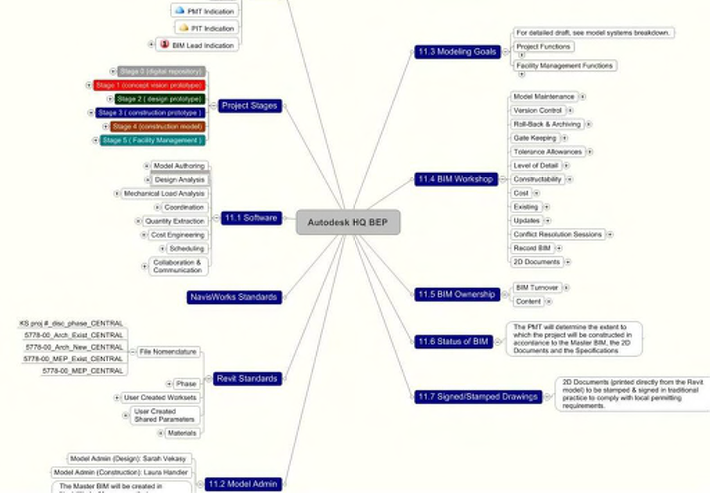
Figure 1: The project’s BIM Execution Plan (BEP) developed by Tocci, KlingStubbins and Autodesk
Before any modeling happened on the project, Sarah & I sat down to establish and negotiate all of our BIM Standards, which we documented in our BIM Execution Plan (BEP), see Figure 01. We had to figure out technical Revit things like worksets, phases, and browser organization, but other, more "social" processes, for instance, protocols for when a central file crashes. We also though out some way to achieve "gate keeping" (translation: to make sure that I didn’t inadvertently move anything I wasn’t working on), but we didn’t end up using any of them because there was so much trust in the team.
One of our major planning activities was merging our individual Revit templates to create a project template. We mostly used the standards we developed and documented in our BEP, but we did run into some issues that we hadn’t considered. For instance, we had to figure out how to handle the project number because we have different project numbers (it actually wasn’t the world’s most creative solution - we just added a parameter for a second project number for Tocci to use).
CO-LOCATING
A key component to integration for the project was co-location. During the design period, I worked two days per week at Kling- Stubbins’ office, at "my" desk next to the design team. Originally, this was only our solution for model-access - whenever I needed to do work in the (our) models, I would just go to work at Kling- Stubbins. Co-locating gave me the opportunity to input content into the model as well as export information, but the majority of my work at KlingStubbins wasn’t actual model contribution. I was able to review and document material selections and options, review schedule and milestones, explain modeling strategy, plan meetings, etc. A lot of this could have been accomplished over the phone (and on the days that I worked in the Tocci office, it was), but it was easier in person (See Figure 2).
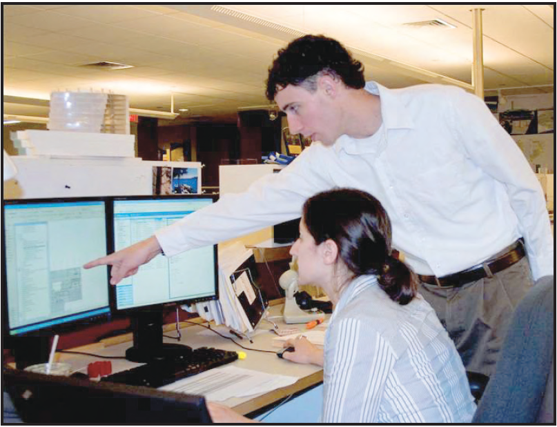
Figure 2: Reviewing the process for modeling walls in three components
More importantly, I really think that it created a sense of team and understanding. During "their" deadline weeks (for instance, permit deadline), I really felt the stress and tension, and on more "fun" days (for instance, the folding paper days during design concept), I was able to understand the concept behind their design. Since I understood why things were happening, I was in a much better position to communicate to other team members at Tocci.
MODELING STRATEGY
Model strategy was big part of our BEP, but some of the items didn’t get resolved for several weeks.
WALLS
We knew from the start that we would eventually model walls as three components, in the method ala construction, but we couldn’t figure out when. We ended up doing it a few weeks before the permit set went out. After a few discussions, we agreed on a multi-step plan to do this. The process was too lengthy to describe, but it started with KlingStubbins doing some organization work in the model with walls (setting wall location as: Core Centerline). Then, I came in and started "breaking". I had a very systematic approach, included both tracking progress and accuracy in Revit and on a printed 2D RCP (with several colors of highlighter, of course).
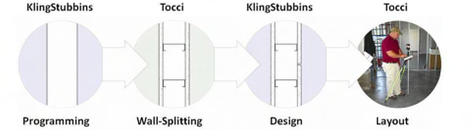
Figure 3: Illustrating the wall breaking concept
The resulting walls were a little bit more difficult to work with, but we made do. Although there were some issues with graphics (in a view set to coarse, the edge of each wall can still be seen, making drawings look "muddy"), I think they made detailing wall sections slightly easier (at least that is what KlingStubbins said!). And the walls made construction much more streamlined; we used the model for partition layout (direct to Total Station) and visual scheduling.
LIGHTING FIXTURES
The lighting fixture debate wasn’t how, but where: in the architecture RVT or the MEP RVT. Architecture places the lights and references them in design documents, but MEP needs to connect to and coordinate with them. We knew that they couldn’t be in both models (for quantity takeoff reasons), but couldn’t figure out the best way to approach them for quite some time.
I won’t get into the heated debate we went through, but luckily, we came to a conclusion just before we needed to start placing them. The lights were placed and annotated in the MEP model, by architecture, and then architecture referenced specific views in the linked files.
ON SITE
Naturally there is a great deal more I could write about our experiences once we got to work on site. I’ll touch on just one for this article. We posted these renderings on site (See Figure 4 and Figure 5), so that the field staff would have a better sense of the overall design intent for the affected areas.
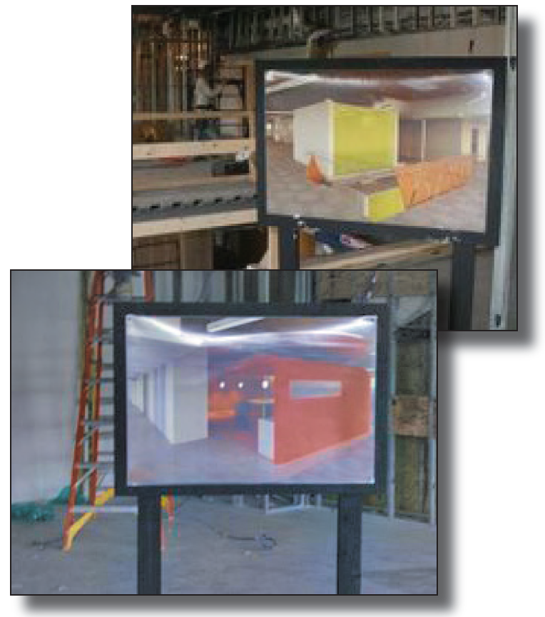
Figure 4 & 5: Renderings installed on-site
For this project, we placed between 12 and 14 renderings on site. Even though we have a shared model with KlingStubbins, these are Tocci-produced renderings. We definitely benefited from the renderings that KlingStubbins did during design because a lot of the custom materials were already set up and we had access to all of the JPGs KlingStubbins used.
It was really exciting to place the boards on site - when I placed them, the drywaller came over and started discussing how the cantilevered piece of the curved wall could be supported as well as the ideal sequence for installing the drywall and the metal ceilings. It was exactly what we were hoping would happen!
Editor’s Note: If you are interested in learning more about this project, Autodesk created a video and it is posted at Youtube. You can watch the video using this link: