AutoCAD Architecture: More Structural Styles
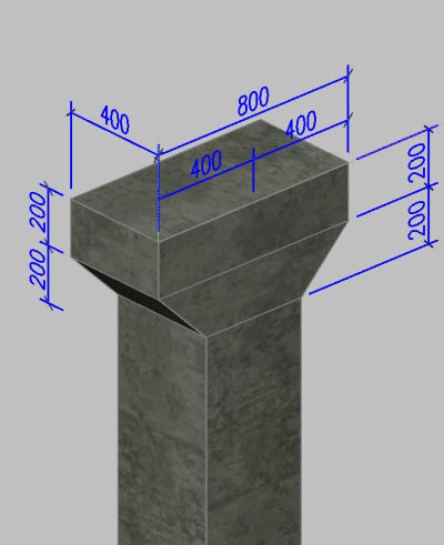
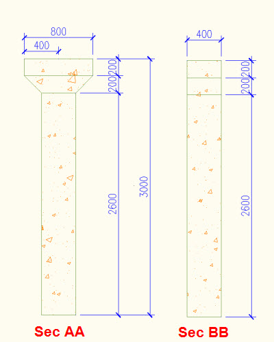
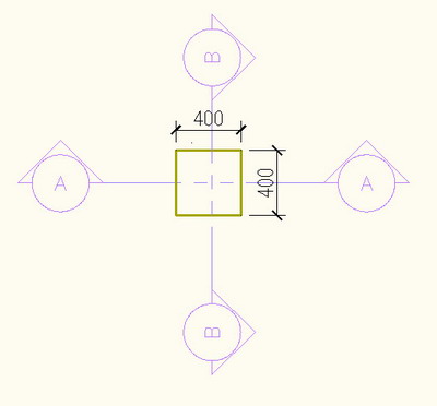
Welcome back! I believe, after going through the few earlier lessons, you are now quite confident with structural member styles. Let's continue our exploration with SM styles. This time, we will create a precast column with a 400x400 I Haunch. Below are some sketches to help you get started.


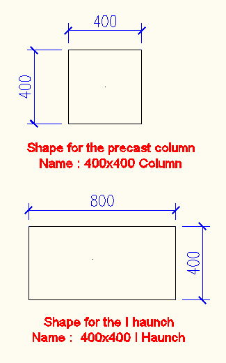
Make sure you start a drawing using a metric template and units set to 'mm.' First, create two structural member shapes as in the sketch below - one for the precast column and one for the I haunch. Name them as shown in the figure. You can refer to my earlier lessons on how to create a structural member shape.

- Create a new structural member style and name it 'Precast Column 400x400 I Haunch.'
- In the right pan of the Style Manager dialog, select the Design Rules tab. You will see the default 'Unnamed' component.
- Click on it and rename it to Main_Shaft.
- Currently the design rule tab shows less detail. Click the Show Detail button at the bottom right. You will see that more details appear for both Start Shape and End Shape. No need to panic. These parameters are quite easy to handle.
We will first define the main column shaft, which has the 400x400 cross section. Later when we change the height of the column, we always want the haunch to stay at the top. We will define the parameters for this main shaft in such a way that the haunch stays at the top.
- Under the Start Shape category, under Name, Click on Standard and from the pull-down select the shape 400x400 column. This was the shape we defined earlier before we started creating the structural member style. Leave the other parameters under the Start shape category as they are.
- Under the End Shape category, check out the shape under Name. You will see that, by default, the shape assigned here is *400x400 column, but the parameters are not editable. So click on the *400x400 column and from the pull down, select 400x400 column shape. Now the parameters are editable.
-
Enter -400 for the X Offset. We are using a negative value as we are defining the position relative to the End. We come down to -400mm and then work our way up.
.jpg)

We are done defining the main shaft component. Before we can proceed defining the haunch component, we need to define a component in between, which is the tapered portion (refer to the sketches above). This portion starts with the 400x400 column shape and will gradually taper towards the 800x400 haunch shape. We will be assigning negative values to the offsets as we are positioning the components, relative to the end of the structural member.
- Click the Add button to add one more component and name it Taper.
Under the Start Shape category
- Under Name, select 400x400 Column as the shape.
- Under Relative To, select End.
- Under X Offset, enter -400. This is because we need to start the taper exactly where the main shaft ends.
Under the End Shape category
- Under Name, select 400x400 I Haunch as the shape.
- Under Relative To, make sure it is set to End.
-
Under X Offset, enter -200. This is because, as per the sketches, the taper has to go up for only 200mm.
Now we can proceed to define the haunch component. This component will have both the start and end shape 400x400 I Haunch. But we need to define the offsets correctly.
- Click the Add button to add one more component and name it Haunch.
Under the Start Shape category
- Under Name, select 400x400 I haunch as the shape.
- Under relative To, select End.
- Under X Offset, enter -200. This is because we need to start the haunch exactly where the taper ends.
Under the End Shape category
- Under Name, select 400x400 I Haunch as the shape.
- Under Relative To, make sure it is set to End.
-
Under X Offset, enter 0. This is because the haunch will have a depth of 200 (-200 start position to '0' end position = 200mm).


- Click 'OK' to close the style manager.
Add a column of this style into the drawing and cross check the dimensions and explore it in a 3D view. Also, try to change the height by grip editing the column and see how the haunch stays right at the top of the column. Use the same logic to create any kind of structural member style that demands multiple cross sections along its length.
Enjoy creating structural member styles. See you all next month!